


1. Introduction
Recently, Wireless Mesh Networks (WMNs) technology has gained a lot of attention and become popular in the wireless technology and the industry fields. This rising popularity is due to its low cost, rapid development and ability to offer broadband wireless access to the internet in places where wired infrastructure is not available or worthy to be deployed [1].
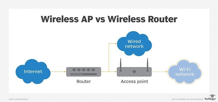
Wireless Mesh Networks (WMNs) consist of mesh routers that collect and forward the traffic generated by mesh clients. Mesh routers are typically fixed and equipped with multiple radio interfaces. Mesh clients are mobile, and data are forwarded by mesh routers to the intended destination. One or more mesh routers may have gateway functionality and provide connectivity to other networks such as internet access, as shown in Fig. ▭. In the WMNs, most of the flows are between the mesh client and the gateway; this kind of traffic is called internet traffic which is the common WMNs traffic as users need to access wired resources.

Gateway discovery approaches in multihop wireless mesh network can be categorized into three categories as follows:
-
Proactive approach: The proactive gateway discovery is initiated by the gateway itself. The gateway periodically broadcasts a gateway advertisement (GWADV). The mesh nodes that receive the advertisement create or update the route entry for the gateway and then rebroadcast the message. Therefore, each node in the WMN are registered with a gateway [2], [3]. The proactive approach provides a good network connectivity and good handoff before losing the connectivity to their original gateway and the gateway routes are always available at all times, which reduces the routing discovery latency. However, this approach imposes a high overhead due to flooding the GWADV message throughout the network.
-
Reactive approach: The reactive gateway discovery is initiated by the mesh router that creates or updates a route to a gateway. The mesh router node broadcasts a Route REQuest (RREQ) message with an “I” flag (RREQ_I) to the gateways. Thus, only the gateways are addressed by this message, and only they process it. When a gateway receives a RREQ_I, it unicasts back a Route Reply (RREP) message with an “I” flag (RREP_I), which, among other things, contains the IP address of the gateway [4], [5], [6]. The advantage of this approach is that the control messages are only generated when a mesh node needs information about a reachable gateway. However, this approach may increase the packet end-to-end delay since the external path is not always available.
-
Hybrid approach: To consider the advantages of the proactive and reactive approaches, they can be combined into a hybrid proactive/reactive method for gateway discovery. For mesh router nodes in a certain range around a gateway, the proactive gateway discovery is used while the mesh router nodes residing outside this range use the reactive gateway discovery to obtain information about the gateway [7], [8], [9]. The approach provides good network connectivity while reducing the overhead. However, the main issue is the optimal value of the advertisement zone.
WMN capacity is reduced by interference from concurrent transmissions. There are two types of interference that affect the throughput of WMN, intra-flow and inter-flow interferences. The intra-flow interference refers to the interference between intermediate nodes sharing the same flow path, whereas, inter-flow interference refers to the interference between neighboring nodes competing on the same busy channel. These come from the half duplex of the radio and the broadcast nature of the wireless medium [10], [11].
Several approaches have been proposed to improve the WMN capacity. One approach is that each mesh router uses a single radio interface that dynamically switches to a wireless channel with a different frequency band to communicate with different nodes [12], [13]. However, this approach increases the routing overhead due to a switching delay. A more practical approach uses multiple radio interfaces that are dedicated to non-overlapping channels [14], [15], [16].
The IEEE 802.11 b/g and IEEE 802.11a standards define three and twelve non-overlapping channels (frequencies) [14], [17], [18]. One of the most important issues for the design of multi-radio multi-channel networks is how to bind the radio interface to a channel in a way that maintains network connectivity. Three approaches have been proposed t solve the channel assignment problem in multi-radio multi-channel WMNs which can be described as flowing:
-
Static channel assignment: In a static channel assignment approach, each interface is assigned to a channel for long time durations. Static assignment can be further classified into two types:
-
Common channel approach: In this approach, the radio interfaces of all nodes in the network are assigned to common channels [19]. For example, if two interfaces are used at each node, then the two interfaces are assigned to the same two channels at every node.
-
Varying channel approach: In this approach, the radio interfaces in different nodes may be assigned to different channels [20], [16]. With this approach, it is possible that the length of the routes between nodes may increase, also, the network partitions may arise due to the inability of different neighbors to communicate with each other unless they assign a common channel.
-
-
Dynamic channel assignment: The dynamic channel assignment approach allows any interface to be assigned to any channel, and interfaces can frequently switch from one channel to another [13]. Therefore, a network using such a strategy needs some kind of synchronization mechanism to enable communication between nodes in the network. The benefit of dynamic assignment is the ability to switch an interface to any channel, thereby, offering the potential to use many channels with few interfaces. However, the key challenges are channel switching delays, and the necessity for coordination mechanisms to switch between node channels.
-
Hybrid channel assignment: In the hybrid approach, all the nodes are equipped with multi-radio interfaces in which the multiple radios are divided into two groups, fixed group and switchable group. In the fixed group, each radio interface is assigned a fixed channel for receiving packets, thereby, ensuring the network connectivity, while the switchable group can dynamically switch among the other data channels [17].
However, most of the previous research focuses on how to answer this question without considering the unique properties of WMNs, which include the following:
-
Most of the traffic in WMNs is designated at the gateways as the users need to access the internet or wired resources. This kind of traffic can be considered as a multi-source single destination traffic.
-
The local traffic and internet traffic must pass through the backbone nodes to reach their destination. Thus, improving the backbone performance will increase the WMN’s performance.
-
Availability of multi-links between adjacent mesh routers makes the mesh routers support simultaneous multi-flow transmission for both kinds of the traffic.
The unique characteristics of WMNs motivated us to developed On-demand Channel Reservation Scheme (AODV-MRCR) with aims to establish high throughput path for the gateway traffic, reduces the interference caused by local traffic, supports full duplex node and only assigns channel to the active node. We achieve these objectives by integrated the reactive routing protocol with channel distribution.
The reactive approach is choosing in order to establish high throughput paths for the gateway traffic and assigns channel to active node. This meaning that all nodes will statically assign common channels to their interfaces, and only the node that has gateway traffic allowed to switch some of its interfaces to the selected channels. Our contributions are as follows:
-
Enhance the capability of the node to receive and transmit concurrently by ensure that distinct channel should be reserved for the reverse and forward routing entry for each node involve in path establish process during the gateway discovery process.
-
Integrated the channel assignment and distribution with the reactive gateway discovery process in order to efficiently utilize the limited number of non-overlapping channel and establish high throughput paths for the gateway traffic.
-
Developed a hybrid interface assignment that reduces the packet collision for the gateway traffic due to the broadcast nature of the wireless medium and existing of local traffic. This done by proposed static and dynamic channel assignment. Static interface assign to static channel and used to support the local traffic while the dynamic interface only assign to active node during the gateway discover process. This interface used to supported gateway traffic.
-
Developed channel assignment that simple (reduce the channel assignment complexity) and independent of any particular profile such as traffic, interference, and topology profile.
The remainder of the chapter is organized as follows. Section two discusses relevant work. The AODV-MRCR protocol is explained in section three. In section four, we provide the details of our simulation environment. Simulation results and their analysis are presented in section five, with concluding remarks in section six.
2. Related works
A major problem facing multi-hop wireless networks is the interference between adjacent links. The throughput of a single-radio single-channel wireless network has been studied in [21]. The authors formalized it as a multi-commodity flow problem with constraints from conflict graph, which is NP hard, and gave an upper bound and a lower bound of the problem.
There have been many studies on how to assign limited channels to network interfaces in a multi-radio multi-channel wireless mesh network as to minimize interference and maximize throughput. They differ in several assumptions made in WMNs, and therefore in the models and related solutions.
One approach assumes a known traffic profile in the network, because the aggregate traffic load of each mesh router changes infrequently. The authors of [20] proposed an iterative approach to solve the joint routing and channel assignment problem. Heuristic techniques are used to estimate the traffic load in each link. The algorithm starts with an initial estimation of the expected traffic load and iterates over both channel assignment and routing until the bandwidth allocated to each virtual link matches its expected load. While this scheme presents a method for channel allocation that incorporates connectivity and traffic patterns, the assignment of channels on links may cause a ripple effect whereby already assigned links have to be revisited, thus, increasing the time complexity of the scheme. Moreover, this approach is performed during the network plan and assumes that the traffic profile is known. The centralized flow-based and rate channel assignment algorithm is proposed in a paper by [22]. The agreed heuristic algorithm is used for channel assignment rate. [23] enhances the [20]centralized algorithm to support automatic and fast failure recovery. The failure recovery mechanism is located at the gateway and all nodes send periodic messages to the gateway. In the case where the gateway does not receive a message during a period of time from node xx, it deletes the corresponding information, node id, position, rate, and then runs the algorithm to update the gateway tables. Based on the new tables, it recalculates the link ranking and channel assignment. However, in general, the centralized approach causes a high computation overhead at the centric node and it is unwieldy in use due to the need for gathering network information. Moreover, most of them are static assignment which is not optimally utilizing the limited number of available non-overlapping channels. In contrast, our approach is a more dynamic approach, which is performed during the real-time networking; in addition, no prior knowledge of the traffic profile is needed.
Other studies assume that the traffic profile of each mesh router is not known, and usually consider channel assignment and routing separately. The authors of [24] assumed that the traffic from the Internet gateway to clients is dominant, and thus proposed distributed channel assignment based on spanning tree topology, where the gateway is the root of the spanning tree. The protocol dedicates one interface channel for communication with its parent node on the tree, and the other interfaces are configured as children for communication with their child nodes. Hence, the protocol divides the node interfaces into two subsets – downlink and uplink interfaces. The uplink interfaces are used to connect the node with its parent node while the downlink is used to connect the node with its child nodes. The node can only switch its child. For channel assignment, the channel assignment strategy starts from the root of the tree. Each node switches its parent interfaces to the parent node child interface and selects a new channel for its child interfaces. One drawback of this protocol is that it only considers the common traffic where data are transmitted from the source to gateway and vice versa.
Multi-channel routing protocol (MCR) [17] the peer-to-peer traffic was assumed to be dominant in the network. The authors first constructed a k-connected backbone from the original network topology, and then assigned channels on the constructed topology. The MCR classified the node interfaces into fixed or switchable interfaces. The protocol assigns a fixed channel to the fixed interface for communication between neighbors, and the remaining interfaces are considered as switchable interfaces. When a node wants to communicate with others, it looks in its table to find the destination’s fixed channel and switches one of the switchable interfaces to that channel. To exchange fixed channels between neighbors, MCR uses a “hello” message to carry the fixed channel information. However, this protocol may not work well in a multi-flow transmission because of high switching interfaces and because it does not utilize all the non-overlapping channels as the static channel assignment uses.
Although there are many distributed solutions proposed in literature [25], [26], [27], [24], [28], [29]. In [25], the authors proposed the Local Channel Assignment (LCA) algorithm, which adopts a tree-based routing protocol for common traffic similar to Hyacinth. The LCA algorithm solved the Hyacinth interface-channel assignment conflict problem which is caused when a parent switches to the least load channel that may be in use by one of its children. The interface-channel assignment problem may cause recursive channel switching and delays. LCA solved this problem by dividing the non-overlapping channel into groups and making each parent interface belong to one group different from its child interface group. The paper of [26] proposed a distributed joint channel assignment and routing protocol for multi-radio multi-channel ad hoc network. The scheme dedicates one interface for the control message and another interface for data transmission. The control interface is assigned to a common channel while the data interfaces could work as a fixed or switchable interface based on the receiving call direction. However, in this approach, the control interface becomes the bottleneck, especially in high-density networks.
In the paper of [27], the authors proposed a hybrid multi-channel multi-radio wireless mesh network architecture, which combines the advantages of both static and dynamic channel allocation strategies. The architecture is similar to Hyacinth architecture [24]; it classifies the interface to work as a fixed interface or a switchable interface. The protocol only considers one interface to work as a switchable interface. This interface has the ability to switch channels frequently, while the remaining interfaces are considered as fixed interfaces that work on fixed channels. The channel allocation of static interfaces aims at maximizing the network throughput from end-users to the gateway, while the dynamic interface is used to communicate with the neighbor node that has a different fixed channel on-demand fashion. Two dynamic interfaces that are within radio transmission range of each other are able to communicate by switching to the same channel when they have data to transmit.
In [28], the authors proposed a learning based approach for distributing channel assignments. It uses a learning based algorithm to determine the best channels to assign its own interfaces based on collecting information from the neighbor nodes. Hence, each mesh node periodically sends a “hello” message in order to discover its neighbors and the channel usage in its neighborhood. The algorithm achieves effective channel usage, and also adapts well to the change of network topology. [29] proposed a distributed channel assignment for uncoordinated WMNs to minimize the interference with adjacent access points. The algorithm assigns the least interference channel to the access point interference according to the gathered channel information from neighboring access points and associated clients. Both the protocols discussed earlier assign channels from node to node, and each node in the WMNs assigns a fixed channel, which makes it different from our approach. In our approach, channel assignment is based on data flow such that a channel is only assigned to a node if it has data to send or forward to the gateway.
The authors of [30] and [26] proposed algorithms to minimize network interference. The first one is interference-aware because it visits the links in decreasing order of the number of links falling in the interference range and it selects the least used channel in that range. Assuming the set of connection requests to be routed, both an optimal algorithm based on solving a Linear Programming (LP) and a simple heuristic are proposed to route such requests, given the link bandwidth availability as determined by the computed channel assignment. The algorithm considers minimum-interference channel assignments that preserve k-connectivity. The algorithm proposed in [26] uses a genetic approach to find the largest number that makes the whole network connected while minimizing network interference. However, such approaches only focus on minimizing the network interference that may decrease the network connectivity. In contrast to the above mentioned approaches, our approach is based on eliminating the interference for the common traffic on WMNs while maintaining network connectivity. Besides static channel assignment algorithms, which assign channels to interfaces without change for a long time, there have been several dynamic channel allocation algorithms proposed, which allow interfaces to switch channels frequently.
The authors of [31] proposed an on-demand channel allocation protocol in a wireless mesh network, where each node has two interfaces. In their framework, one interface of each node is devoted to controlling channel negotiation only while the other interface is used for data transmission. On the other hand, the frameworks proposed in [32] and [12] do not require a separate control interface, and the channel negotiation happens on the same interface for data transmission.
The Channel Assignment Ad hoc On-demand Distance Vector routing (CA-AODV) [33], has been proposed to assign channels within K hops in an ad hoc network, allowing for concurrent transmission on the neighboring links along the path and effectively reducing the intra-flow interference. Similar to CA-AODV, [34] proposed to join the channel assignment with the AODV. The source node needs to ensure the channel selection by sending two messages. The first message is to inform neighbors about the selected channel and the second message is sent by the neighbors to confirm the channel. In case the channel is in use, the node should be waiting until the channel is free or selects a new channel. However, such an approach may not work well in WMNs where most of the traffic is directed toward the gateways and must pass through mesh routers.
3. Multi-radio ad hoc on-demand distance vector routing with channel reservation scheme
The Multi-radio ad hoc on-demand distance vector routing with channel reservation scheme (AODV-MRCR) protocol is a multi-radio on demand distance vector routing protocol, which is proposed to establish high throughput paths for the gateway traffic in WMNs.
Our scheme uses on-demand reactive routing protocol to distribute the reserved channels list among all the nodes along the path from the source to the gateway. The source node that does not has fresh route to the gateway, it sends RREQ with flag set to one which means only the gateway can reply this message. Once the gateway receives a new RREQ_I, it selects a reserved channel list and attaches to the RREP_I message. The message is sent back to the source node. During the RREP_I stage, each intermediate node selects its recommend channel based in the hop count index[35]. The intermediate node reserves at least two interfaces for the gateway path, one link for the forward path and other for reverse path.
We assume that mm channels are available that can be used in a wireless area without interfering. In addition, kk channels of available channel are statically assigned to ii interfaces, half of kk channels are used as “used channels”, and the m−k/2m-k/2 channels will be considered as “unused channels”. The iiavailable interfaces at each node can be classified as:
-
Fixed interfaces: Some nn of the ii interfaces at each node are assigned for long intervals of time to kk channels, we designate these interfaces as “fixed interfaces”, and the corresponding channels as “used channels”. These interfaces are used to keep the network connectivity as well as support the local traffic. Therefore, they are not allowed to switch.
-
Switchable interface: The reaming i−ni-n interfaces are switched to the selected channels for long intervals of time. These interfaces are assigned to a channel that is selected from the range m−k/2m-k/2 channels during the RREP_I message.
For example, if the mesh router has four interfaces, two channels of twelve (1, 2) will be considered as used channels. The reaming channels will be considered as unused channels. Moreover, the interfaces one and two will be considered as fixed interfaces while the interfaces three and four are switch- able interfaces. The scheme consists of two parts. The first part is carried out at the gateway, which is used to reserve a unique list of channels for each RREQ_I received at the gateway. The second part is carried out when the intermediate nodes along the path back to the source receive the RREP_I message. Following is a clarification of the procedures.
3.1. CHANNEL RESERVATION SCHEME
Channel reservation scheme is carried out into two stages. First stage is carried out by the gateway, which is used to reserve a unique list of channel for each received RREQ_I message, see algorithm 1. The second stage is carried out when the intermediate nodes along the path back to the RREQ_I source node receive RREP_I message, which is aims to distributed the channel along the active nodes, see algorithm 2.
Once the gateway receives a new RREQ_I message, it checks the channel reservation table for the RREQ_I source address entry. Each table entry contains the source node address and reserved channel list for each received RREQ_I.

When the intermediate node receives the RREP_I message, it creates/updates the forward route entry with the recommended channel as indicated in RREP_I’s recommended channel. Then, it selects a channel from the RREP_I’s list based on the hop count. The intermediate node selects the channel only if it satisfied the following constrains.
-
The RREP’s reserve channel list is not empty
-
At least there is one interface work on fixed channel to support the local traffic.
If the intermediate nodes along the forward path are satisfied the above constraints, a recommended channel will be selected based on the hop count modular the number of channel in the reserve channel list as shown in Fig. ▭.

In case it matches, the corresponding entry is attached to the RREP_I and send back along the reverse path to the RREQ_I source node. However, if no entry found, then the gateway randomly select a new reserved channel list from the unused channel list, update the channel reservation table and attach the list to the unicast RREP_I.
▭ explains the channel selection at the gateway. Two RREQ_I messages from source node (SS) received at the gateway through different paths. The path with minimum hop count will be selected as the best path toward the source node (SS). The gateway (GG) checks the channel reservation table for the source node address (SS). If a match is found, the corresponding entry is attached to the RREP_I message. If not found, a new reserve channel list will be selected and attached to the RREP_I message. The maximum number of the channel in the reserve channel list is four channels [35]. The reserve channel list along with recommend channel is attached to the RREP_I message and is sent back to the RREQ_I’s source node.
In this figure, the gateway selects the channel at location zero. This is because the hop count at the gateway is zero. Once the message receives at the next hop, the hop count will be one and the result of modular operation point to the location one in the reserve channel list, and so. When the hop count exceeds the maximum number of channel in the reserve channel list, such as node six, the recommended channel will be selected based on the modular operation which will point to location zero. However, In case the above constraints are not satisfied, the node sets the RREP’s recommended channel to zero and forward the message to next hop, see algorithm 2.

3.2. CHANNEL SWITCHING AND NEGOTIATION
The proposed protocol is an across layer protocol that integrated the channel assignment and routing protocol with the MAC layer. The routing protocol is used to select the reserved channel list for each received RREQ_I at the gateway and distribute them among the nodes along the path from the source to the destination. Moreover, the four handshake, rts-cts-data-ack, MAC messages are used by the proposed protocol in order to coordinate the channel switching between pair of nodes and ensure that both nodes have been switched to the selected channel (recommended channel) same as proposed in [31], [18].

Fig. ▭ describes the channel switching and negotiation, when the intermediate node receives the RREP_I message, it sends the message to the MAC layer using the reverse route entry interface field. Then the MAC layer sends a RTS message including the channel information to the neighboring nodes. The neighboring nodes, which work on the same channel as the sender, will receive the RTS message; upon receiving the RTS message, the receiver sends back a CTS message. Once the source node receives the CTS message, it starts sending the RREP_I packet. If the node receives ACK or the transmission time has expired, it switches the interface to the new channel. At the receiver side, the receiver replies with an ACK and waits for the transmission time to expire when it receives data. After that, it switches the interface to the new channel.
4. Simulation environment
Since our protocol is multi-radio mutli-channel routing protocol that take into consideration the availability of multi-radio per mesh router as well as the multi-channel, We evaluate the performance of AODV-MRCR compared to AODV-MR [36] and MCR [17] using ns-2 [37]. The former AODV-MR is developed to enhance the reactive routing protocol to support the multi-radio and take into account the advantage of multi-links between mesh routers. The protocol uses ICA channel assignment where each mesh router has multi-radio interfaces, which statically dedicated to non-overlapping channel. The latter MCR routing protocol is developed to utilize the multi-channel where each node randomly selects a channel from the none-overlapping channels. The selected channel is assigned to an interface. This interface is considered as fixed interface for communication between neighbors and the remaining interfaces are considered as switchable interfaces. The switching mechanism is used to exchange the message between neighbors. When a mesh router has a data to send, it switches one of its switchable interfaces to the distention’s fixed channel. AODV-MR and MCR protocols distribute the channels based on unknown knowledge profile similar to our protocol. Moreover, they are based on the reactive routing discovery process in order to discover the path. When the node has data to send, it sends RREQ message and waits for receiving RREP message. Every intermediate node receives RREQ, it creates a reverse path and forwards the message to all interfaces. Once the destination receives the RREQ message, it replies with RREP message back to the RREQ’s source node.
A mesh network on an area of 1000×10001000×1000 meter22 a 2-dimensional open area, without any building or mountain, was established using a random distribution mesh routers. Hence, a simple two-ray-ground propagation model [38] is used. All nodes are randomly distributed and each node is equipped with multiple wireless interfaces that statically turned to non-overlapping channels using the same channel allocation scheme. At the MAC layer, IEEE 802.11 DCF with RTS/CTS collision avoidance is used since we used the four hand check to distribute the channel between pair nodes along the path from source to destination. The channel switching latency is set to 80μμs [33]. The common parameters for all the simulations are listed in Table 1.
TABLE 1.
Simulation parameters
4.1. PERFORMANCE METRICS
The simulation provides the following five performance metrics:
-
Packet Delivery Ratio(PDR): The ratio between the number of data packets successfully received by the destination nodes and the total number of data packets sent by the source nodes.
-
Aggregate goodput: The total number of application layer data bits successfully transmitted in the network per second.
-
End-to-end delay of data packets: The delay between the time at which the data packet originated at the source and the time when it reaches the destination. It includes all of the possible delays caused by queuing for transmission at the node, buffering the packet and retransmission delays. This metric represents the quality of the routing protocol.
-
Routing overhead: The ratio of the total number of packets generated to the total number of data packets that are successfully received.
-
Packet loss: The number of packets that were lost due to unavailable or incorrect routes, MAC layer collisions or through the saturation of interface queues.
5. Simulation results and discussion
To evaluate our protocol, we carried out two simulations with different scenarios, as follows.
5.1. SIMULATION 1:COMPARE OUR PROTOCOL WITH MULTI-RADIO ROUTING PROTOCOL
In this simulation, the efficiency of AODV-MRCR compared to AODV-MR [36] was evaluated using ns-2 [37]. Each mesh router is equipped with four wireless interfaces that statically turn to non-overlapping channels using the same channel allocation scheme. Concurrent UDP flows are established between the randomly selected source and the gateway while keeping the other parameters, as in Table 1. We run AODV-MRCR with twelve non-overlapping channels, and AODV-MR with four channels statically dedicated to the node interfaces. We carry out different scenarios to show the various factors affecting the performance of our protocol. The scenarios are: varying the number of flows, effect of number of radio per node, and evaluating the performance of the protocol using TCP traffic.
5.1.1. SCENARIO 1: VARYING NUMBER OF THE FLOW
In this scenario, we investigate the impact of traffic load in the network. The number of generated flows varied from 10 to 50 flows with increments of 10. The packet size for each connection was fixed to 512 bytes with a 20 packet per second data rate. Fig. ▭ (a-d) shows the packet loss, aggregated goodput, PDR and end-to-end delay performance. As observed from Fig ▭, performance of the AODV-MRCR is comparable to that of the AODV-MR at a lower traffic load, such as 10 or 20. This is because AODV-MR can utilize the four channels to minimize the number of links on the same channel within the path as well as create channel diversity along the path.

However, when the flow increases, the network becomes saturated. Thus, the AODV-MR end-to-end delay and packet loss increase as shown in Fig. ▭(a, d) while the PDR and aggregated goodput decrease (Fig. ▭(b, c). This is because AODV-MR is unable to avoid the congestion area as it does not have an intelligent way to route the packet through a less congested area. Moreover, minimum channel diversity cannot achieve due to using the hop count as a metric. In contrast, ▭ shows an improvement in the performance of the AODV-MRCR under increasing traffic load relative to the AODV-MR. In addition, it shows that the lower packet losses incurred by our protocol enables it to achieve a significantly higher packet delivery ratio.
This is because the protocol assigns a unique list of channels to every RREQ_I received at the gateway during the route-establishing stage. Hence, the single collision domain divided to many collision domains as the number of flows increase.
Fig. ▭(d) As the number of the flows increase, our protocol achieves better average end-to-end delay than the AODV-MR. This is because our reservation scheme allows the AODV-MRCR protocol to assign different non-overlapping channels for each node for the gateway traffic. Resulting in, reduces the contention time at the MAC layer as well as allowing the node to receive and send simultaneously. Moreover, It is interesting to note that at high traffic load such as 50 flows, the AODV-MR’s end-to-end-delay (Fig. ▭(d)) reduces compare to other flows such as 30 and 40 flows. The reason for that is at high traffic load the network is saturated and the aggregated throughput exceeds the actual bandwidth, hence the collision probability of the multi-hop packets becomes high as the number of flows increases. Accordingly, a few multi-hop packets will be received at the destination while most of the received packets are single hop packets.
5.1.2. SCENARIO 2: EFFECT OF NUMBER OF RADIO PER NODE
▭ depicts the performance of AODV-MR and proposed algorithm versus the number of radio. The number of radios in each mesh router is varied from three to eight in increments of one along with all other simulation parameters, as per Table 1. This scenario carried out to determine the optimal number of radios to be placed in each mesh router. The results shown in Fig. ▭ show that AODV-MR has an improvement in performance up to eight radios in each mesh router. The reason for this is that AODV-MR cannot utilize all the non-overlapping channels, unless they are assigned to the interface. Hence, adding a new interface to the mesh router means adding a new channel to the AODV-MR spectrum utilization.

Fig. ▭ also shows that a limited number of radios per node, about 7, are sufficient for AODV-MRCR to achieve its maximum performance improvements. However, increasing the number of radios beyond seven seems to only achieve a marginal improvement. This result obviously depends on the number of available channels, which are used to choose the reserved channel list for each RREQ_I received at the destination. The AODV-MRCR statically assigns a unique channel for each mesh router interface and half of these channels consider as used channel. Consequently, increasing the number of interfaces per mesh router, minimizes the non-distributed channels in the unused channel list, which increase the packet loss ratio, see Fig. ▭(a). However, increase the number of interfaces per node lead to minimize the number of channel in the unused channel list which leads to increase the inter-flow and intra-flow interferences for the gateway traffic. Moreover, increasing the intra-flow and inter-flow interference leads to increase in the packet end-to-end delay due to an increase in the MAC contention time and packet retransmission at the MAC layer, see Fig. ▭(d). In all of the cases considered, AODV-MRCR performs significantly better than the AODV-MR routing protocol.
5.1.3. SCENARIO 3: VARYING TCP TRAFFIC
We study the performance of the AODV-MRCR and AODV-MR when there are 100 nodes distribute on area of 100 1000×10001000×1000 meter22 and twelve of non-overlapping channels. Table 1 shows the simulation parameters for this scenario.
We analyze the performance of the proposed protocol in two main scenarios. In the first scenario, we study the effective of TCP traffic load by varied the number of the flow from 10 to 50, and in the second scenario, we varied the packet size from 128 to 1440 bytes.
Fig. ▭ shows the performance of the proposed protocol and the AODV-MR. The results of Fig. ▭show that the AODV-MR achieves poor performance as the number of flows or the packet size increases. This result occurs because AODV-MR suffers from many problems. First, it used hop count metric as path selection metric, hence, AODV-MR not being able to avoid the hot spot area, it may also select paths with small channel diversity and route the packet through high-congestion areas. The result is that the links frequently get saturated and suffer from multi-flow interference.
Second, the AODV-MR using the same route and same channel to forward the TCP data and the acknowledgement, which leads to an increased Round Trip Time (RTT).

FIGURE 6.
Simulation 1: results for scenario 3 test TCP traffic (Varying the number of flows and Varying packet size).
In contrast, The AODV-MRCR minimizes the packet round trip time by assignees different channels for reverse and forward routes per node, which allows the node to become a full-duplex node. This procedure reduces the contention and transmission time at the MAC layer. Moreover, the AODV-MRCR assigns a unique list of channels for each flow received at the destination, which leads to minimizing the interference and reducing the packet drops due to packet collision, enabling the route to be effective for long durations while minimizing the number of route discovery messages.
Fig. ▭(c, d) shows the performance of both protocols when varying the packet sizes. Our protocol outperforms AODV-MR in terms of aggregate throughput and routing overhead as the packet size increases. This is because our protocol reduces the round trip time at the intermediate node and reduces the transmission time. Reducing the RTT time leads to an increase in the network throughput due to the TCP packet generation depends on successfully receiving ACKs. Furthermore, similar to [39], Fig. ▭shows that a larger packet size can lead to an increase in link failure at the MAC layer. Similarly, a small packet size can reduce the duration of capture, resulting in frequent opportunities for channel access. However, a small packet size also increases the control overhead and can increase the number of collisions at the link layer.
5.2. SIMULATION 2: COMPARE OUR PROTOCOL WITH MULTI-RADIO MULTI-CHANNEL ROUTING PROTOCOL
In this simulation, we compare the performance of our protocol with the performance of the MCR routing protocol [17]. Many centralized approaches have been proposed to assign a channel to node interfaces in multi-radio multi-channel networks. Most of these approaches need a global view of the network such as traffic profile or node position. Even though, our approach is a centralized approach that establishes high throughput paths for the gateway traffic, it does not require prior knowledge about the network. The MCR routing protocol is multi-radio multi-channel routing protocol that is similar to our protocol in some aspects, such as, it randomly selects a channel with no prior knowledge about the network and uses the routing management messages to inform the neighbors about the selected channel. For all scenarios, varying number of flows, varying packet size, studying the impact of node density, studying the impact of local traffic, and varying the number of non-overlapping channels available in this simulation, we keep the number of interfaces per mesh router to three interfaces and each interface is statically dedicated to a channel using the common channel assignment approach. We carried out different scenarios as described below:
5.2.1. SCENARIO 1: VARYING NUMBER OF THE FLOWS
In this scenario, we evaluate the impact of varying the number of the flows in the network. The number of CBR flows is varied from 10 to 50 with an increment of 10 flows. We keep the other parameters as in Table 1. Under heavy traffic load beyond twenty flows, the proposed approach performs better than MCR as shown in Fig. ▭. Moreover, with high traffic load, the MCR end-to-end delay increases as the number of concurrent flows increase see Fig. ▭(c). This is because the MCR routing protocol adds extra delay overheads for every received packet.

In contrast, our protocol reduces the packet end-to-end delay. This is due to the fact that in proposed scheme, a node becomes full duplex transmission. Furthermore, the scheme only assigns channel to the active nodes, which considerably reduces the interference and contention time at the MAC layer and hence the delay reduces. The delay increment has direct impact in the aggregated goodput and number of packet loss see figure. Hence, increase the number of packet loss lead to increase in the of control message. Since the MCR routing protocol sends a copy of the broadcasting message on every channel, the MCR overhead (RREQ, RREP, HELLO) increases as the number of the flows increases as show in Fig. ▭(d).
However, our protocol sends a copy of broadcasting message on all node’s interfaces; in a multi-channel network the number of channels are more than the number of interfaces. Moreover, our protocol does not use the hello message to inform the neighbors about the node channel, as in the MCR. This is because our scheme distributes the channel to the nodes involved in the path during the routing discovery process.
5.2.2. SCENARIO 2: VARYING THE NUMBER OF AVAILABLE CHANNELS
To investigate the impact of the number of channel in AODV-MRCR, we varied the number of available channels from 5 to 12. The other simulation parameters are fixed as in Table 1.
Fig. ▭ shows the results of the MCR with respect to the AODV-MRCR for a different number of available channels. As observed from Fig. ▭(b), AODV-MRCR shows higher PDR than MCR regardless of the number of channels. The performance difference becomes large with the increase in the number of channel. The reason of this performance improvement of AODV-MRCR is can be explained by the fact that adding more channel will increase the number of concurrent transmission. Moreover, using more channels allows our protocol to maximize the channel diversity along the path as well as minimize the channel use between multiple concurrent transmission flows. However, as the number of channels increases, the node interface becomes congested which can limit the MCR performance. This is because that the MCR routing protocol spent more time by the switchable interface in sending broadcast packets.
It is interesting to note that at 5 available channels, our protocol has a higher routing overhead than the MCR routing protocol. This is because our protocol selects the reserved channel list from the unused channel list. However, small available channels while keeping the number of interfaces per mesh router at three will minimize the number of channels in the unused channel list. For example, at 5 available channels the unused channel list will be four channels, as at least one channel will be used to keep the network connectivity and to support the local traffic.

5.2.3. SCENARIO 3: IMPACT OF LOCAL TRAFFIC

To investigate the impact of the local traffic on the gateway traffic, we varied the number of the peer-to-peer traffic from 5 to 20 flows. The number of the gateway traffic is the subtraction of the total number flows (50 flows) in the network and number of the local traffic per each scenario. The simulation parameters for this scenario are as shown in Table 1. Fig. ▭ shows the end-to-end delay and PDR for both peer-to-peer and gateway traffic. This figure Shows that as the local traffic increase, the AODV-MRCR improves both type of the traffic and still can get higher results than MCR. The figure also shows that the AODV-MRCR’s performance metric for gateway traffic does not decrease when the number of the local traffic increase. The improved performance of AODV-MRCR can be explained as following. Our protocol differentiates between the local traffic and internet traffic by reserve a list of channels for the gateway traffic and these channels cannot be used to transmit the peer-to-peer traffic. Moreover, the AODV-MRCR protocol assigns different channel for the reverse and forward path which lead to better channel diversity than MCR routing protocol. Fig. ▭ also shows that for the local traffic( peer-to-peer) of ten flows, the performance of both protocols in term of PDR and end-to-end delay are decreased. The reason for that is the randomly distributed traffic between mesh router nodes as well as the node random distribution may cause the traffic to be located in the same area.
6. Conclusion
In this chapter, we proposed a channel reservation scheme, which establishes a high throughput path for the gateway traffic by utilizing the WMN characteristics, such as multi-radio mesh router and most of the traffic toward the gateway. The channel reservation and assignment are integrated with the gateway routing discovery process. This scheme reduced the influence of local traffic on the performance of the gateway traffic. Moreover, the scheme minimized the number of nodes using the channel by only assigning channels to the node that is involved in the gateway path route discovery process. The performance of the proposed scheme is evaluated with respect to the metrics, such as packet delivery ratio, end-to-end delay, aggregate throughput, packet loss and routing overhead. The results obtained show that the proposed scheme is better than the existing schemes with respect to these metrics. Currently, the protocol designed in this chapter is mainly for infrastructure wireless mesh networks, which assumes that most of the traffic is towards the gateway. This proposed protocol could be further enhanced to support a more general wireless network, such as hybrid wireless mesh network. Moreover, it can be enhanced by assigning the channel to traffic based on the traffic load. Another possible extension is to consider multiple transmission rates. Different transmission rates can be achieved by using different modulation schemes, for example, IEEE 802.11b transmissions support four different data rates 1Mbps, 2Mbps, 5.5Mbps, and 11 Mbps. Finally, the proposed protocol can be further investigated with different MAC protocols for different radio interfaces.
Acknowledgement
The research was partially supported by the Research University, FRGS /1/11/SG/UPM/01/1